
New Products
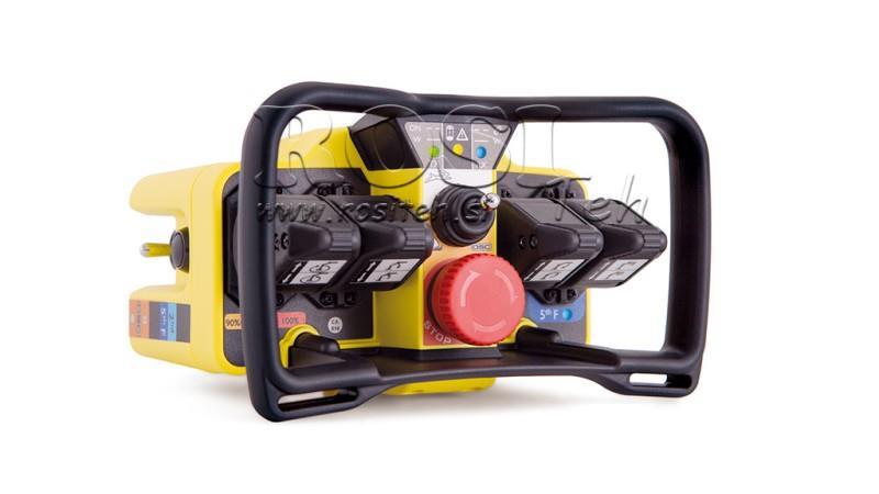


RADIO REMOTE CONTROLLER - PROPORTIONAL - KRON M4+1 10012 PLUS
FUNCTIONS ENABLED BY RADIO CONTROL:
The label 'M4+1' or 5th function is a function for controlling the fifth direction (5th movement - side button) of the crane, which shares the same lever typically used for standard movement. It is used in specific cases such as special lifts, clamps, or pairs of grapples) or generally a function that requires safer activation (dedicated additional button).
The label Rabbit / Snail is a speed function, where rabbit allows 100% output speed on all levers, while snail allows 50%.
The label DSC (Dynamic speed control) is a function that in 'snail' mode allows the operator to temporarily increase output power (speed). With this function, you can increase or decrease speed, and these settings remain until the receiver is turned off. When you turn the receiver back on, the speed returns to the default values assigned to 'snail'.
The label IN-SLOW is a digital input intended for lifting platforms (those on which operators are). If this pin is activated (usually a mechanical switch that automatically activates when the lifting platform is mounted on the crane), all movements go directly to 10% speed, and only one movement is allowed at a time. This complies with specific standards for lifting platforms.
The label RPM +/- usually increases the number of engine revolutions, increasing oil pressure, thus making the crane's speed faster or slower.
The label MOTOR on/off is a function intended for the truck's engine (if supported).
The label LIGHTS on/off is an additional output on the receiver for controlling the truck's lights (if supported), allowing the operator to work in the dark.
The label Load indication 90%/100% is a function that is combined with crane data management with feedback. If the crane supports this function, we can receive information that the load exceeds 90% and/or 100% of the load, in which case an LED light on the transmitter lights up.
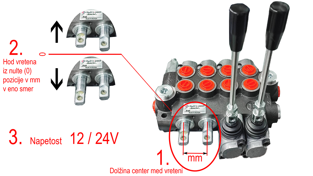
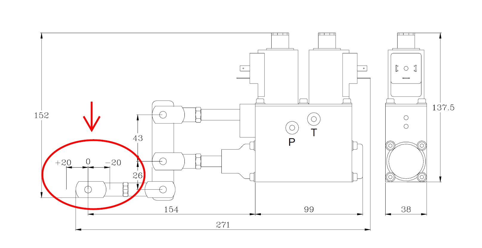
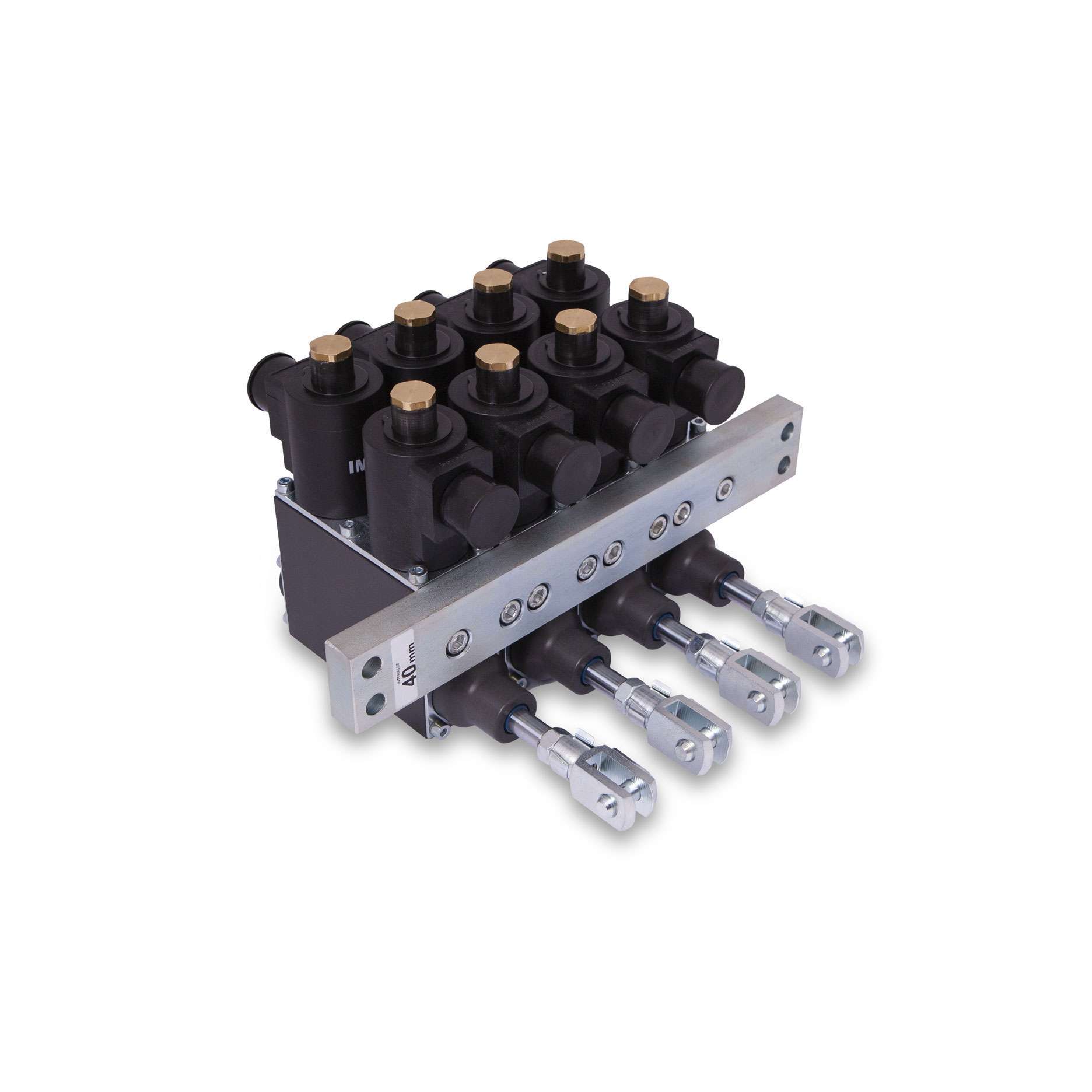
IMPORTANT: For correct configuration and operation of the radio proportional controller, please provide us with the data for the following three items from the photo below:
1. Length center between spindles, defined distance from the center of one spindle to the next spindle center - given in mm.
2. Stroke of the spindle from the zero (0) position in mm in one direction, defined distance for moving the spindle in one direction from the starting position (0) when the lever is moved in one direction - given in mm,
3. Voltage 12/24V, defined source of power supply voltage - 12V or 24V.
EXTENSION OF THE STROKE OF EACH SEGMENT:
For spindle strokes up to 13 mm, the extension of each segment is not required. The dimensions are as follows (example for a stroke of 13 mm in each direction):
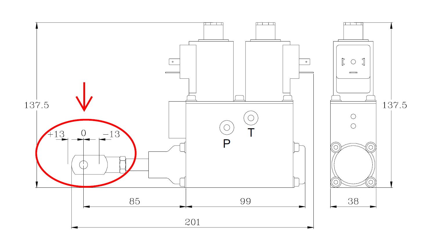
For spindle strokes over 13 mm, an extension is required EXTENSION OF THE STROKE OF EACH SEGMENT (12-20mm) FOR VALVE. This applies to each segment individually. As many segments as there are, that many extensions need to be added. If you have four spindles, then four extensions are required. The dimensions are as follows (example for a stroke of 20 mm in each direction):
|
|
 |  |
Video:


